Zero Liquid Discharge Systems

Zero Liquid Discharge Systems

Zero Liquid Discharge (ZLD) is a treatment process designed to remove all the liquid waste from a system. The focus of ZLD is to reduce wastewater economically and produce clean water that is suitable for reuse (e.g. irrigation), thereby saving money and being beneficial to the environment. ZLD systems employ advanced wastewater/desalination treatment technologies to purify and recycle virtually all of the wastewater produced.

The conventional way to reach ZLD is with thermal technologies such as evaporators (multi stage flash (MSF), multi effect distillation (MED) and mechanical vapour compression (MCV)) and crystallizers and recover their condensate. Thus, ZLD plants produce solid waste.

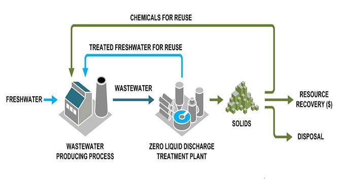
Also ZLD technologies help plants meet discharge and water reuse requirements, enabling businesses to:

  • Meet stringent government discharge regulations
  • Reach higher water recovery (%)
  • Treat and recover valuable materials from the wastewater streams, such as potassium sulphate, caustic soda, sodium sulphate, lithium and gypsum

Despite the variable sources of a wastewater stream, a ZLD system is generally comprised by two steps

(a) Pre-Concentration: Pre-concentrating the brine is usually achieved with membrane brine concentrators or electro dialysis (ED). These technologies concentrate the stream to a high salinity and are able to recover up to 60–80% of the water.

(b) b) Evaporation/Crystallization : Pre-concentrating the brine is usually achieved with membrane brine concentrators or electro dialysis (ED). These technologies concentrate the stream to a high salinity and are able to recover up to 60–80% of the water.

Multi Stage Flash Evapourators (MSF)

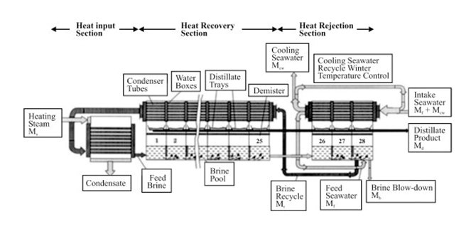
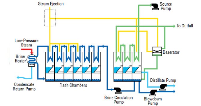
An evapourator consists of several consecutive stages (evapourating chambers) maintained at decreasing pressures from the first stage (hot) to the last stage (cold). Sea-water flows through the tubes of the heat exchangers where it is warmed by condensation of the vapour produced in each stage. Its temperature increases from sea temperature to inlet temperature of the brine heater. The sea water then flows through the brine heater where it receives the heat necessary for the process (generally by condensing steam). At the outlet of the brine heater, when entering the first cell, sea water is overheated compared to the temperature and pressure of stage 1. Thus it will immediately "flash" ie release heat, and thus vapour, to reach equilibrium with stage conditions. The produced vapour is condensed into fresh water on the tubular exchanger at the top of the stage.

The process takes place again when the water is introduced into the following stage, and so on until the last and coldest stage. The cumulated fresh water builds up the distillate production which is extracted from the coldest stage. Sea water slightly concentrates from stage to stage and builds up the brine flow which is extracted from the last stage.

The once-through flash type evapourator uses the sea-water flow both for purposes of cooling (sea-water is introduced into the evapourator at the sea temperature and is rejected at the brine temperature) and production of distillate (by flashing from the outlet temperature of the brine heater to the brine extraction temperature). This has two consequences on plant design:

  • The whole sea water flow being heated to high temperature, it has to be treated with anti-scale which increases operating costs.

  • As the sea water flow cannot be decreased below values allowing safe working conditions, the stages must be designed for winter operation, leading to an increased evapourator volume and thus increased investment costs.

The cooling sea-water flows through the condensers of the two (or generally three) last stages, named "heat reject section". Upon leaving the evapourator, part of the warmed water is rejected to the sea, part is used as the make-up for the plant. Only this part of the water is treated instead of the whole cooling water. The production is insured by the brine recycling flow that is drawn from the last stage towards the condensers of the other stages, named "heat gain section", and then to the brine heater.

The warmed water leaving the heat reject section may be used in winter to warm up the cooling sea-water, thus enabling the evapourator volume to be designed for a reasonably high temperature.

MSF plants with brine recycling are widely used all over the world. Once-through desalination plant should only be used for small plants (when the cost of the chemicals is not of great importance) and in areas where the temperature of the sea-water remains approximately constant throughout the year.

Multi-effect distillation (MED)

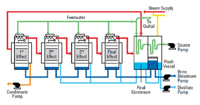
Multiple-effect distillation or multi-effect distillation (MED) is a distillation process often used for sea water desalination. It consists of multiple stages or "effects". In each stage the feed water is heated by steam in tubes, usually by spraying saline water onto them. Some of the water evapourates, and this steam flows into the tubes of the next stage (effect), heating and evapourating more water. Each stage essentially reuses the energy from the previous stage, with successively lower temperatures and pressures after each one. There are different configurations, such as forward-feed, backward-feed, etc. Additionally, between stages this steam uses some heat to preheat incoming saline water.


The plant can be seen as a sequence of closed spaces separated by tube walls, with a heat source in one end and a heat sink in the other end. Each space consists of two communicating subspaces, the exterior of the tubes of stage n and the interior of the tubes in stage n+1. Each space has a lower temperature and pressure than the previous space, and the tube walls have intermediate temperatures between the temperatures of the fluids on each side. The pressure in a space cannot be in equilibrium with the temperatures of the walls of both subspaces. It has an intermediate pressure. Then the pressure is too low or the temperature too high in the first subspace and the water evapourates. In the second subspace, the pressure is too high or the temperature too low and the vapour condense. This carries evaporation energy from the warmer first subspace to the colder second subspace. At the second subspace the energy flows by conduction through the tube walls to the colder next space.

The thinner the metal in the tubes and the thinner the layers of liquid on either side of the tube walls, the more efficient is the energy transport from space to space. Introducing more stages between the heat source and sink reduces the temperature difference between the spaces and greatly reduces the heat transport per unit surface of the tubes. The energy supplied is reused more times to evapourate more water, but the process takes more time. The amount of water distilled per stage is directly proportional to the amount of energy transport. If the transport is slowed down, one can increase the surface area per stage, i.e. the number and length of the tubes, at the expense of increased installation cost.

The salt water collected at the bottom of each stage can be sprayed on the tubes in the next stage, since this water has a suitable temperature and pressure near or slightly above the operating temperature and pressure in the next stage. Some of this water will flash into steam as it is released into the next stage at lower pressure than the stage it came from.

The salt water collected at the bottom of each stage can be sprayed on the tubes in the next stage, since this water has a suitable temperature and pressure near or slightly above the operating temperature and pressure in the next stage. Some of this water will flash into steam as it is released into the next stage at lower pressure than the stage it came from.

The first and last stages need external heating and cooling respectively. The amount of heat removed from the last stage must nearly equal the amount of heat supplied to the first stage. For sea water desalination, even the first and warmest stage is typically operated at a temperature below 70-75 °C, to avoid scale formation.

Mechanical Vapour Compression Evapourator (MCV)

Vapour-compression evaporation is the evaporation method by which a blower, compressor or jet ejector is used to compress, and thus, increase the pressure of the vapour produced. Since the pressure increase of the vapour also generates an increase in the condensation temperature, the same vapour can serve as the heating medium for its "mother" liquid or solution being concentrated, from which the vapour was generated to begin with. If no compression was provided, the vapour would be at the same temperature as the boiling liquid/solution, and no heat transfer could take place.

It is also sometimes called vapour compression distillation (VCD). If compression is performed by a mechanically driven compressor or blower, this evaporation process is usually referred to as MVR (mechanical vapour recompression). In case of compression performed by high pressure motive steam ejectors, the process is usually called thermo-compression or steam compression.

Since compression of the vapour increases both the pressure and temperature of the vapour, it is possible to use the latent heat rejected during condensation to generate additional vapour. The effect of compressing water vapour can be done by two methods. The first method utilizes an ejector system motivated by steam at manometric pressure from an external source in order to recycle vapour from the desalination process. The form is designated electro-compression or thermo-compression.

Using the second method, water vapour is compressed by means of a mechanical device, electrically driven in most cases. This form is designated mechanical vapour compression (MVC).

The MVC process comprises two different versions: vapour compression (VC) and vacuum vapour compression (VVC). VC designates those systems in which the evaporation effect takes place at manometric pressure, and VVC the systems in which evaporation takes place at sub-atmospheric pressures (under vacuum).

The compression is mechanically powered by something such as a compression turbine. As vapour is generated, it is passed over to a heat exchanging condenser which returns the vapour to water. The resulting fresh water is moved to storage while the heat removed during condensation is transmitted to the remaining feedstock.