The 800 KLD STP at Golf link Embassy Business Park named Torrey Pines STP is currently operating based on Activated Sludge Process with fluidized bed reactor. 7 separate buildings are connected to this STP. The plant was running smoothly during the initial stages as the inflow to the plant was far below the design capacity as the buildings had not been occupied completely. Later on, when the occupancy reached close to 80 percent, the plant was unable to process the inflow properly due to high variations in the inflow fluid parameters and variation in the peak inflow rate.
- Home
- Knowledge Centre
- Case Studies
- 800 KLD FBR+ASP TO 1000 KLD MBR
800 KLD FBR+ASP TO 1000 KLD MBR
ABSTRACT

Due to which, the treated water parameters reached much beyond the permissible limits. The filters in the plant were been choking more frequently. The tenant repeatedly changed the filter media, both sand and carbon filters, for improved performance, but has not been successful in attaining the treated water parameters as per the norms. A team approached the plant for identifying the problems in the plant and it was found that the major problems were at the primary and secondary treatment stages itself. The inlet was having more oil content and the time of aeration was not sufficient due to peak inflow. It was forced to fill the aeration tank at more rates which was resulting in the disturbance in the entire system.
CHAPTER 1
EXISTING PROCESS: ACTIVATED SLUDGE PROCESS WITH MOVING BED BIO-REACTOR

The existing plant is located near Torrey Pines has an approximate floor area of 515 m2. The plant has a processing capacity of 800 m3/day. It uses Fluidized Bed Reactor (FBR) technology. FBR employs RING PAC MEDIA, neutrally buoyant bio film carrier elements, to achieve outstanding BOD/COD removal productivity from a compact bioreactor. In Fluidized Bed Reactors, the liquid to be treated is pumped through a bed of small media at a sufficient velocity to cause fluidization. In the fluidized state the media provide a large specific surface for attached biological growth and allow biomass concentrations in the range 10-40 kg/m3 to develop. For aerobic treatment processes the reactor is aerated using fine bubble diffusers connected to air blowers.The basis for the use of fluidized bed systems is the immobilization of bacteria on solid surfaces. Many species of bacteria (and also other microorganisms) have the ability for adhering to supporting matrices.
In this process, a volume of Ring Pac media is immersed in water and is fluidized (kept in constant motion) through the movement of gas and liquid in the treatment reactor. As the media supports a biomass concentration several times that achievable in activated sludge systems, treatment is significantly more productive.Flocculator and clarifier are employed for settling the sludge and separating the water and sludge. Sand filters and Carbon filters are used for subsequent filtration. But the main problem of these kind of plants is regulation of MLSS in the nominal range. For sludge handling a Filter press is currently used in the plant which has a very low sludge handling capacity. The deviation from the nominal range will cause BOD variations in the water and colour difference which results in clarity issues. Also there may not be any consistency in water clarity in the long run due to ageing of bacteria.
CHAPTER 2
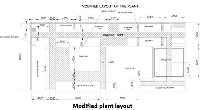
PROPOSED MODIFICATION
The proposed modification mainly includes upgrading the plant to MBR technology. The disturbances occurring due to the peak inflow will be managed by merging the existing equalization tank and sludge holding tank and thereby, expanding the raw sewage holding capacity. Then again the inflow will be fed to existing secondary clarifier. The clarifier mechanism will be replaced and the entire tank will be converted to anoxic tank.
For the conversion of the plant to MBR based plant, few tanks have to be modified.
The new tanks which are needed in the plant are:
- MBR tank
- Anoxic tank
The main tank is the MBR tank in which the MBR modules have to be submerged. We have selected the FBR tank which is currently in the plant for converting into the MBR tank. The FBR tank meets the minimum volume requirement needed for MBR tank. Usually, the size needed for MBR tanks will be very low compared to other tanks in the plant.
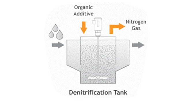
Simply adding bacteria to a wastewater plant does not guarantee that they will achieve the targeted task of denitrification. To encourage their growth, it is essential to first establish an anoxic environment, and then introduce a mixer that has been optimized specifically for the process.
Denitrification in wastewater treatment is the conversion of nitrate (N03) to nitrogen gas (N2). It is a process that involves the reduction of nitrogen present in waste streams to an acceptable level so the treated water can be discharged into the environment via streams, ponds, lakes, etc. Lowering nitrate levels in a waste stream is achieved through creating an anoxic environment in which heterotrophic bacteria use nitrate as an oxygen source to break down organic substances.
In the denitrification process, an anoxic zone is created by using an unaerated tank where the dissolved oxygen levels are kept below 1 mg/L and as close to, without reaching 0 mg/L as possible. A target operating point would be between 0.2 to 0.5 mg/L. The concentration of mixed liquid and suspended solids must also be kept in balance. The pH of the anoxic zone should be close to neutral (7.0) and never drop below 6.5.
Heterotrophic bacteria obtain their oxygen through the following sequence: free and dissolved oxygen, nitrate, and then sulfate. When deprived of readily available oxygen, as in an anoxic environment, bacteria will use nitrate as an oxygen source to break down carbon, their source of food. During denitrification, the tank is agitated but not aerated, thereby starving the bacteria of readily available oxygen. This forces the bacteria to break down the nitrate in the activated sludge to use as their primary oxygen source.
For the anoxic tank we have selected the clarifier tank currently in the plant. The clarifier tank already has the clarifier mechanism which is similar to anoxic agitator, except, the speed of rotor for anoxic agitator should be more and the clarifier rotor should be replaced with an agitator fan.
Tank Sizes
| SL. NO: | NAME | ACTUAL SIZE (m) |
|---|---|---|
| 1 | BAR SCREEN CHAMBER | 5 x 1 x 1 |
| 2 | EQUALISATION TANK | (15 x 5.3 x 5) + (10 x 2 x 5) |
| 3 | AERATION TANK | 17 x 5 x 5 |
| 4 | ANOXIC TANK | 7 x 7 x 5 |
| 5 | MBR TANK | 5.05 x 5 x 5 |
| 6 | FINAL TANK | 10 x 7.55 x 5 |

CHAPTER 3
TORREY PINES – EXPANDING TO 1000 KLD
By operating at the peak operating flux, the volume of wastewater that can be processed is as follows:
For HSMM 800 ES,
| Peak operating flux | = 51 L/m2hr |
| Filtration area for one module | = 800 × 2 = 1600 m2 |
| No. of modules | = 2 |
| Total filtration area available | = 800 × 2 = 1600 m2 |
Total volume processed in a day
| (in 20 hrs) | = peak operating flux × filtration area × operating hours |
| = 51 × 1600 × 20 | |
| = 1632000 L / day | |
| = 1632 KLD |
For processing 1000 KL in a day, the operating flux should be reduced
| Operating flux | = process capacity/ (filtration area × operating hours) |
| = 1000000 / (1600 × 20) | |
| = 31.25 L/m2hr |
CHAPTER 4
PROPOSED PLANT DETAILS
BAR SCREEN
A bar screen is a mechanical filter used to remove large objects, such as rags and plastics, from wastewater. It is part of the primary filtration flow and typically is the first, or preliminary, level of filtration, being installed at the influent to a wastewater treatment plant. They typically consist of a series of vertical steel bars spaced between 1 and 3 inches apart.
Bar screens come in many designs. Some employ automatic cleaning mechanisms using electric motors and chains, some must be cleaned manually by means of a heavy rake. Items removed from the influent are called screenings and are collected in dumpsters and disposed of in landfills. As a bar screen collects objects, the water level will rise, and so they must be cleared regularly to prevent overflow.
Modifications:
The bar screen in the plant has no modifications and will be used for the modified plant also.
EQUALIZATION TANK
Usually, sewage generation is more during morning hours and evening hours. Visually no sewage is generated during night hours. Any biological system needs constant feed for bacteria to work efficiently. Hence, it is important to put an equalization tank to collect the excess flow during peak hours and feed sewage in lean hours. A typical equalization tank has a capacity of 8 – 12 hours of average flow rate. The tank is generally of civil construction by client. Provision of air grid is to be made for thoroughly mixing the sewage to make it of homogenous quality and to keep the suspended matter in suspension and to avoid septic conditions.
Modifications:
In the existing plant we have an equalisation tank with a capacity around 390 KL. Since we are increasing the plant capacity and also for managing shock flows in the future, we are increasing the equalisation tank capacity by merging the existing sludge holding tank with the equalisation tank. A total of 100 KL increment will be there in the equalisation tank capacity. Core cutting will be employed at the bottom wall for merging the tanks. Repair of diffusers in both tanks will be also done.
FINE SCREEN
Fine screens are typically used to remove material that may create operation and maintenance problems in downstream processes, particularly in systems that lack primary treatment. Typical opening sizes for fine screens are 1.5 to 6 mm (0.06 to 0.25 in). Very fine screens with openings of 0.2 to 1.5 mm (0.01 to 0.06 in) placed after coarse or fine screens can reduce suspended solids to levels near those achieved by primary clarification.
Modifications:
One fine screen is already available in the plant which will be shifted to proposed anoxic tank. Pipeline modifications are needed for transferring sewage water to the fine screen.
ANOXIC TANK
For the anoxic tank we have selected the clarifier tank currently in the plant. The clarifier tank already has the clarifier mechanism which is similar to anoxic agitator, except, the speed of rotor for anoxic agitator should be more and the clarifier rotor should be replaced with an agitator fan.
Modifications:
The clarifier tank will be modified into anoxic tank with agitator fan. Over flow line to the filter feed tank will be blocked and new over flow line to the aeration tank from the anoxic tank will be made.
AERATION TANK
Sewage liquor is run into deep tanks with diffuser grid aeration systems that are attached to the floor. These are like the diffused aerators used in tropical fish tanks but on a much larger scale. Air is pumped through the blocks and the curtain of bubbles formed both oxygenates the liquor and also provides the necessary mixing action. Where capacity is limited or the sewage is unusually strong or difficult to treat, oxygen may be used instead of air. Typically, the air is generated by some type of blower or compressor. Aeration brings water and air in close contact in order to remove dissolved gases (such as carbon dioxide) and oxidizes dissolved metals such as iron, hydrogen sulfide, and volatile organic chemicals (VOCs). Aeration is often the first major process at the treatment plant.
Modifications:
The already existing aeration tank will be used for the modified plant also. It has a capacity of nearly 450 KL. The diffusers will be checked are repaired and line damages will be corrected. RAS line modifications will be done to transfer sludge from aeration tank to MBR tank. Overflow line connecting aeration tank and existing FBR tank will be closed. MLSS will be ranging from 8000-12000 mg/L.
MBR TANK
Membrane bioreactor (MBR) is the combination of a membrane process like microfiltration or ultra filtration with a biological wastewater treatment process, the activated sludge process. When used with domestic wastewater, MBR processes can produce effluent of high quality enough to be discharged to coastal, surface or brackish waterways or to be reclaimed for urban irrigation. Other advantages of MBRs over conventional processes include small footprint, easy retrofit and upgrade of old wastewater treatment plants. Membrane bioreactors can be used to reduce the footprint of an activated sludge sewage treatment system by removing some of the liquid component of the mixed liquor. This leaves a concentrated waste product that is then treated using the activated sludge process.
Modifications:
The existing FBR tank will be used as MBR tank. It has a capacity of 125 KL. Existing air lines and diffusers in the tank will be kept for MBR modification and all lines will be repaired. Overflow line from MBR tank to the aeration tank will be made by employing core cutting. Separate blowers will be installed for MBR air supply. Centrifuge line for sludge transfer will be provided at the bottom.
For HSMM 800 ES,
The existing final sump will be used without any further modifications. It has a capacity of 350 KL.
CHAPTER 5
HSMM 800-ES MBR INSTALLATION
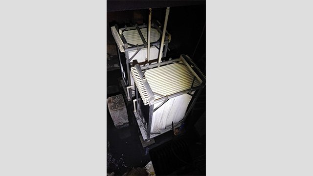
MBR testing with domestic water
2 modules of HSMM 800-ES were installed in the plant with total of 40 membrane elements. After installing the MBR modules, the tank is filled with fresh water and trial runs were made in fresh water starting with minimum VFD set point and trial runs were gradually varied from minimum set point to full load in fresh water itself. Permeate automation testing was started afterwards with a filtration time of 4 minutes and relaxation time of 1 minute, with the PID set point as 25 m3/hr. The filtration time gradually set to 7 minutes after testing for some cycles of operation.
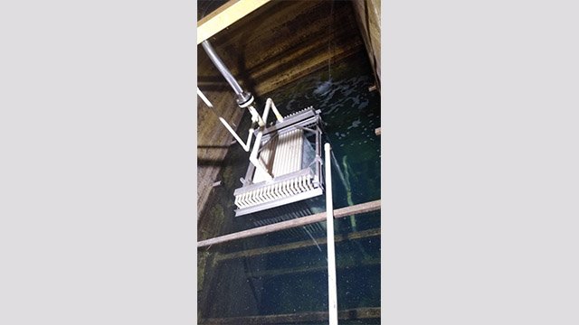
MBR testing with domestic water
After successful trial runs, the aeration tank feed from raw water tank were controlled by monitoring the newly installed inlet flow meter (Aster Magflow 650) and controlling the recirculation valve connected in raw water line. After stabilizing the flow, the MBR tank is filled with the help of RAS pump. The PLC controlled panel is used for starting the plant in automatic mode. Due to reduced inflow during the test time, it was easy to test run the plant and identify the defects. The MLSS was maintained just above 8000 mg/L. The test run with sewage water was carried with actual running time parameters but at 25 m3/hr flow rate. The PID loop with VFD will control the pump so that the flow rate will be constant throughout the cycle. A pressure transmitter is connected to monitor the membrane pressure and the data is continuously fed back to the PLC. As the membrane fouling increases the pressure will increase as the permeate pump will try to maintain the flow rate by increasing the RPM through VFD.
Buzzer and trip points are set based on pressure to do periodic cleaning activities without fail. The maximum flow rate set was 40 m3/hr, which is below the design capacity and the increment in this flow rate was reached in 6-8 days. Since the inflow doesn’t cross 800 KLD, The PID set point of 40 m3/hr was more than enough and the observed TMP during this maximum 0.186 bar as per the data from the pressure transmitter.
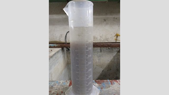
MLSS check
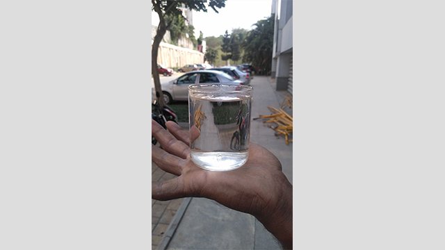
The final water without adding any chlorine or UV treatment was found to be crystal clear and transparent, without any colour or smell. A chlorine sensor is installed in the permeate discharge line and the dosing rate will be changed as per the chlorine sensor signals to the pump. The treated water test reports show that the upgraded plant is running successfully and the parameters are well within the limits set by the authorities.
Treated water from MBR
CHAPTER 6
WATER QUALITY COMPARISON
Inlet water parameters
| Sl no: | Parameter | Value | Unit |
|---|---|---|---|
| 1 | pH | 7.6 | - |
| 2 | TSS | 190 | mg/L |
| 3 | BOD | 378 | mg/L |
| 4 | COD | 370 | mg/L |
| 5 | Total Nitrogen | 14 | mg/L |
| 6 | Ammonical Nitrogen | 7 | mg/L |
| 7 | Total Phosphorous | 5 | mg/L |
| 8 | Fecal Coliform | 106 | MPN/100mL |
Treated water parameters
| Sl no: | Parameter | KSPCB Standard | Before Upgradation | After Upgradation | Unit |
|---|---|---|---|---|---|
| 1 | pH | 6.5-9.0 | 7.42 | 7.31 | - |
| 2 | TSS | <20 | 16.0 | 0.81 | mg/L |
| 3 | BOD | <10 | 8.8 | 3.1 | mg/L |
| 4 | COD | <50 | 45.0 | 15.8 | mg/L |
| 5 | Total Nitrogen | <10 | 24.8 | 5.3 | mg/L |
| 6 | Ammonical Nitrogen | <5 | 7.9 | <0.1 | mg/L |
| 7 | Total Phosphorous | - | 6.4 | <0.1 | mg/L |
| 8 | Fecal Coliform | <100 | 70 | absent | MPN/100mL |
CONCLUSION
The MBR upgradation completed successfully. The old 800 KLD STP at Golf link Embassy Business Park named Torrey Pines STP is currently operating based on MBR technology with an increased processing capacity of 1000 KLD without any increase in size of the tanks or without any new tanks construction. The merging of excess tank which were used in ASP, but now has no use due to upgradation, has been done and by doing so, the fluctuating and peak inflow problems were eliminated and the process is highly stabilized as per standard. The insufficient aeration has been rectified by cutting off air supply from other plants and replacing new tubular fine bubble diffusers. The main aeration blower is now supplying air to equalization and aeration tank only. The introduction of new MBR air blower helped to attain this condition. After complete installation and trial runs, the plant had been brought to full capacity over a period of 7 to 8 days starting from minimal load. The required MLSS range was achieved during these days with the help of fresh bacteria and additional urea/DAP mixture. The treated water from the plant has been sent out for quality testing and it has been found that the quality was excellent both in terms of visibility and contents. The Project was successfully handed over to the client eliminating all the initial problems.